Eulag
Eulag
All-Scales Geophysical Research Model |


 |
|
below is a set of conditions specific for this test case:
      parameter (n=128,m=64,l=51)                ! grid dimensions
      parameter (dx00=10.)
      parameter (dy00=10.)
      parameter (dz00=10.)
      parameter (dt00=0.25)

      parameter (nt=600,noutp=10,nplot=10,nstore=600,nslice=0)
      parameter (iwrite=0,iwrite0=0,irst=0)

      parameter (nt=1440,noutp=288,nplot=288,nstore=720,nslice=0)
      parameter (iwrite=1,iwrite0=0,irst=0)

      parameter (icyx=1)
      parameter (icyy=0)

      parameter (implgw=1,isphere=0,icylind=0,icorio=0)

#define SGS 1      /* 0=NO DIFFUSION, 1=OLD DISSIP, 2=DISSIP AMR      */
      parameter (icyy=1)
      parameter (ivs0=1)                          ! Viscous/Inviscid model
      parameter (itke0=1,itke=ivs0*itke0)         ! Smagorinsky/TKE SGS model

      parameter (ichm=1,nspc=1)              ! chemical spices
      parameter (imrsb=1)

ccccccccccccccccccccccccccccccccccccccccccccccccccccccccccccccccccc
create environmental profiles (use subroutine tinit_i)            c
c-----------------------------------------------------------------c
c---> u00 - wind constant; x component, profile U       (m/s)     c
c---> v00 - wind constant; y component, profile V       (m/s)     c
c---> st  - stability parameter; inverse scale height   (m^-1)    c
c---> u0z - vertical wind shear dU/dz                   (s^-1)    c
c---> v0z - vertical wind shear dV/dz                   (s^-1)    c
ccccccccccccccccccccccccccccccccccccccccccccccccccccccccccccccccccc
      data     u00,    v00,     st,    u0z,    v0z
     $        /10.0,   0.0, 1.0e-5,  0.e-3,  0.e-3/

ccccccccccccccccccccccccccccccccccccccccccccccccccccccccccccccccccc
create mountain
c-----------------------------------------------------------------c
c     amp  - maximum height of mountain [m]
c     xml  - zonal scale of mountain [m] or [radians]
c     xml0 - zonal shift from the domain center [m] or [radians]
c     yml  - meridional scale of mountain [m] or [radians]
c     yml0 - meridional shift from the domain center [m] or [radians]
c     angle- angle to skew the mountain ridge [radians]
ccccccccccccccccccccccccccccccccccccccccccccccccccccccccccccccccccc

      common/gora/ xml,yml,amp,xml0,yml0,angle
      data amp,xml,yml,xml0,yml0,angle/100.,2*100.,-200.,0.,0./
Following are other case specific setups
C initialization of the passive source of the tracer.

      do ispc=1,nspc
      do k=1,l
      do j=1,mp
      do i=1,np
      .....
       chm(i,j,k,ispc) = 0.
      fchm(i,j,k,ispc) = 1000.0

Setup orographical features inside subroutine topolog

      rd(xln,ylt)=sqrt(((xln-xml0)/xml)**2+((ylt-yml0)/yml)**2)
      rb(xln,ylt)=sqrt(((xln+xml0)/xml)**2+((ylt+yml0)/yml)**2)
      rc(xln,ylt)=sqrt(((xln     )/xml)**2+((ylt-xml0)/yml)**2)

      profm(rad)=.5*(1.+cos(pi*rad))

Setup for the lower topography "zs(n,m)":

      xx= cang*(x(ia)-x0)+sang*(y(ja)-y0)
      yy=-sang*(x(ia)-x0)+cang*(y(ja)-y0)
      rr=rd(xx,yy)
      zs(i,j)= 0.
      zs(i,j)=amp*cvmgm(0.,profm(rr),1.-rr)
      ...

Setup for the mmersed boundary object "szib2(n,m)":

      gij=zb/(zh(i,j)-zs(i,j))           ! define terrain following transformation
      zloc=(k-1)*dz                      ! compute unstretched uniform height
      zcrl=zloc/gij+zs(i,j)              ! height in terrain following coordinates

      zsib(i,j,k)=-1.                    ! default, no IMB points
      xx= cang*(x(ia)-x0)+sang*(y(ja)-y0)
      yy=-sang*(x(ia)-x0)+cang*(y(ja)-y0)
      if(itopo.eq.0) rrb=rb(xx,yy)       ! object shifted in X
      if(itopo.eq.1) rrb=rc(xx,yy)       ! object shifted in Y
      zsib2(i,j)=amp*cvmgm(0.,1.,1.-rrb)

      if(zcrl.lt.zsib2(i,j)) then        ! check if grid height below object
        zsib(i,j,k)=1.                   ! add IMB points below zsib2 surface
      endif
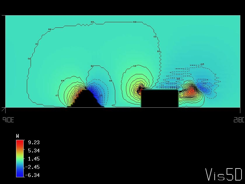
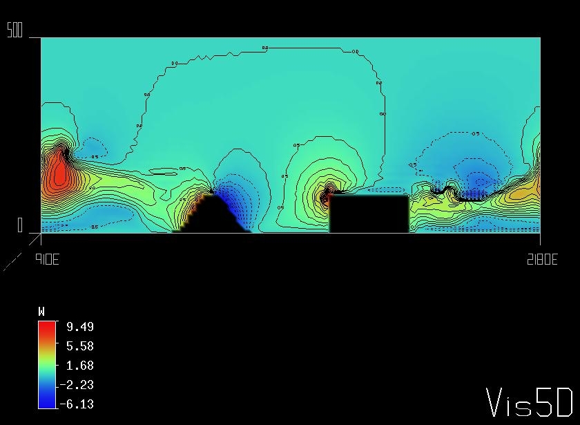
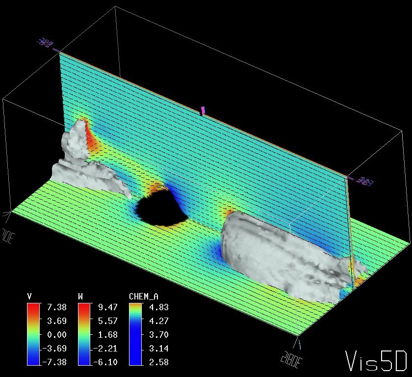
Figure 1 snd Figure 2 shows the vertical velocity fields after t=8 sec and t=30 sec respectively. The cross sections of the U, W velocity components and the isosurface of the passive tracer are presented at Figure 3. |