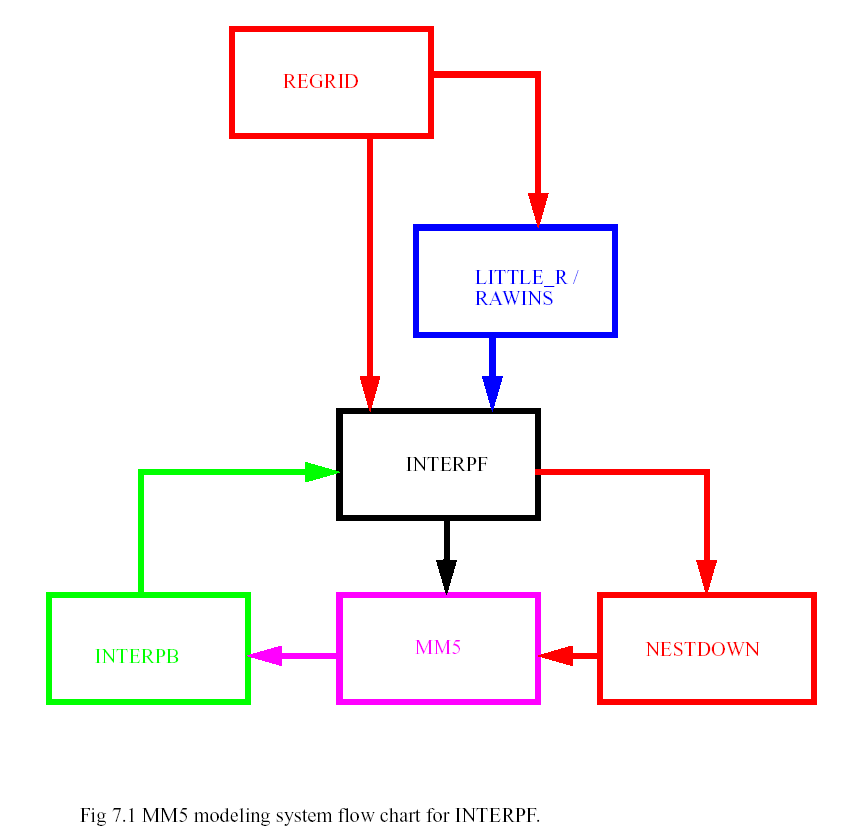
The INTERPF program handles the data transformation required to go from the analysis programs to the mesoscale model. This entails vertical interpolation, diagnostic computation, and data reformatting. INTERPF takes REGRID, RAWINS, LITTLE_R, or INTERPB output data as input to generate a model initial, lateral boundary condition and a lower boundary condition.
The INTERPF program runs on the following platforms: HP/Compaq/Alpha, Cray, Fujitsu, HP, IBM, SGI, Sun, PCs running Linux (Fedora with PGI or Intel compilers), and MAC (OSX with xlf). The INTERPF code is written in FORTRAN 90.
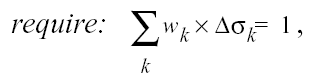
Please note that the "X" used in the following computations throughout the entire chapter signifies an arithmetic multiplication, not a cross product.
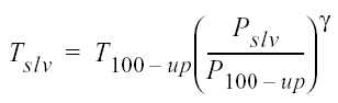
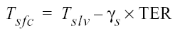
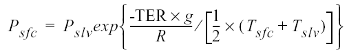
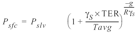
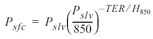
1. first guess for representative T, p 100 hPa above surface
 |
(7.1) |
 |
(7.3) |
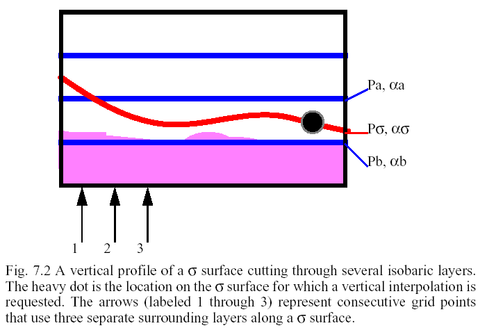
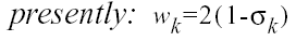
The process of going from pressure levels to the σ coordinate requires only strictly bounded interpolation. Since the σ coordinate is defined to be contained within the maximum and minimum pressure, no extrapolations are required. A generated surface field is available as a coding option inside INTERPF via the namelist. Vertical interpolation uses linear techniques exclusively, typically linear in pressure or linear in ln pressure.
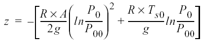
Hydrostatic pressure is defined as
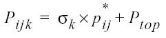 |
(7.7) |
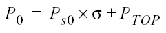
where σ is a 1-D vertical coordinate, σ =1 at the ground, σ =0 at the model lid; p* is the arithmetic difference of the 2-D field of surface pressure and a constant (Ptop); and Ptop is the constant pressure at the model lid.
 |
(7.8) |
Removing the integrated mean divergence allows the model to begin with a smaller amount of initial condition noise that the analysis contains. Given the average upper-air station separation, the reasonableness of the high frequency, column-averaged vertical motion is spurious at best. Again, the computations are scalar, and the "X" signifies scalar multiplication.
1. pressure weighted u, v on each σ
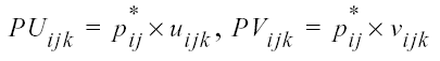 |
(7.9) |
3. divergence of vertically-averaged pressure-weighted wind [m is the map scale factor for dot (D) and cross (X)]
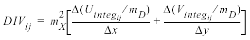 |
(7.11) |
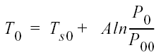
The base state for the MM5 model is constructed from several constants prescribing a surface level temperature and pressure, a temperature profile which may include an isothermal layer above the tropopause, and analytic expressions for a reference pressure and the height of the non-hydrostatic σ surfaces. Other than the terrain elevation only these constants are required by the modeling system as user input to completely define the base state.
 |
(7.17) |
This provides a fixed (in time) height for each σ surface, since each i,j,k location is a function of the fixed σ values and the terrain elevation.
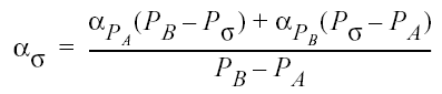
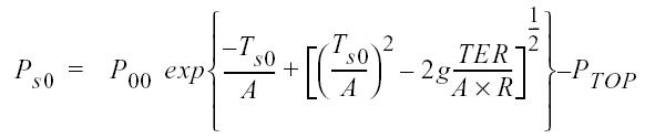
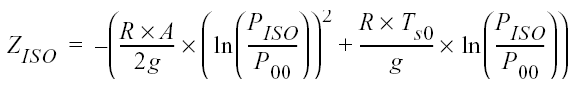
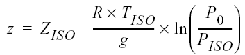
If the user has requested the use of the isothermal temperature option from the namelist, the temperature and height computations are modified. First, the minimum temperature allowable is defined as the isothermal temperature. The pressure at the location for the switch to the isothermal temperature is computed. From this pressure (PISO), the isothermal height is found, and then the adjusted reference height.
 |
(7.21) |
 |
(7.22) |
INTERPF first generates a hydrostatic input file on the hydrostatic sigma levels which is based on actual surface pressure, not reference pressure. To initialize the data for the nonhydrostatic model a further small vertical interpolation is needed to move to the nonhydrostatic sigma levels. This involves first calculating the heights of the hydrostatic levels, then doing a linear-in-height interpolation of u, v, T and q to the nonhydrostatic levels.
While sea-level pressure, u, v, T and q are known from the input data sets, the nonhydrostatic model requires two more variables to be initialized.
There are three primary binary output files from the INTERPF program: MMINPUT_DOMAINn, BDYOUT_DOMAINn and LOWBDY_DOMAINn. The MMINPUT_DOMAINn file contains the time dependent 3D and 2D fields, such as wind, temperature, moisture and pressure. The BDYOUT_DOMAINn file contains the lateral boundaries of the 3D fields, typically, four rows worth of data. The LOWBDY_DOMAINn file contains either daily means of, or time-varying surface temperature fields (surface air temperature and sea surface temperature), and optionally sea-ice and snow cover fields.
The surface air temperature is either the temperature field defined at the surface from the input pressure-level data set (typically), or the lowest σ-level temperature field (if the namelist option was set to not use the input surface data in the vertical interpolation). This field is used as the constant, deep-soil temperature whenever the land surface model is not selected. The variable used as the sea surface temperature in REGRID is not well defined. Based on user selections, the sea surface temperature could be the water temperature, the skin temperature or the 1000 hPa temperature. Users with high resolution land use may find that they have very "hot" lakes during the summer.
If the user selected the skin temperature from the PREGRID Vtable, a daily mean of both the surface air temperature and the sea surface temperature are computed and output in the LOWBDY_DOMAINn file. The purpose for the daily mean is to reduce the diurnal variation of the "constant" temperature and provide more realistic inland lake temperatures. This is the reason it is recommended that users always prepare an analysis/forecast that extends for at least a full day. If the user selected the SST from the PREGRID Vtable, then the INTERPF program automatically provides time varying fields of both SST and the surface air temperature. When in doubt, the user should assume that that temperature at the ground is the skin temperature and not suitable for use as a time varying field for SST.
All of the MM5 system job decks for IBM are written as C-shell executables. Strict adherence to C-shell syntax is required in this section.
|
location of MSS files, keep same as used for deck generating input file for this program |
|
Most of the available options for the INTERPF code are handled through the namelist input file. Since this file is a FORTRAN namelist (FORTRAN 90 standard), syntax is very specific. There are six namelist records (record0 through record5). In general, all of the namelist records must be filled with the user's description of the data.
1) Obtain the source code tar file from one of the following places:
ftp://ftp.ucar.edu/mesouser/MM5V3/INTERPF.TAR.gz
/MESOUSER/MM5V3/INTERPF.TAR.gz
2) gunzip the file, untar it. A directory INTERPF will be created. cd to INTERPF.
3) Type `make' to create an executable for your platform.
4) On an NCAR IBM, edit interpf.deck.ibm (located in ~mesouser/MM5V3/IBM) to select script options and to select namelist options. On workstations, edit the namelist.input file for the namelist options.
5) On an NCAR IBM, type interpf.deck.ibm to compile and execute the program. It is usually a good practice to pipe the output to an output file so that if the program fails, you can take a look at the log file. To do so, type: interpf.deck.ibm >& interpf.log, for example. On a workstation, run the executable directly (interpf >& interpf.log).
INTERPF requires one of the following input files: REGRID_DOMAINn, RAWINS_DOMAINn, LITTLE_R_DOMAINn, or MMOUTP_DOMAINn (where n is the domain identifier). The location for the input data, including directory structure, is defined in the namelist file.
Output files from INTERPF (input files for MM5): MMINPUT_DOMAINn, BDYOUT_DOMAINn, LOWBDY_DOMAINn (where n is the domain identifier). These files are output in the current working directory. The user has no control over this naming convention.
The interpolation program has input and output files that are ingested and created during an INTERPF run. The binary input files and all of the output files are unformatted FORTRAN write statements (binary, sequential access). One of the input files is a human-readable namelist formatted file of run-time options.
The following tables are for the input and output units.
|
MM5 system, meteorological data on pressure levels, input to INTERPF |
|
lower boundary condition (reservoir temperature, mean or time-varying SST, sea ice, fractional seaice, snow cover) |
The interpf.tar file contains the following files and directories:
CHANGES |
Description of changes to the INTERPF program |
Doc |
Contains a couple of README files |
Makefile |
Makefile to create INTERPF executable |
README |
General information about the INTERPF directory |
interpf.deck.cray |
job deck for usage on one of the NCAR Cray machines |
namelist.input |
input namelist file for run-time options |
src/ |
INTERPF source code |