____________________________________________________________________________________________
____________________________________________________________________________________________
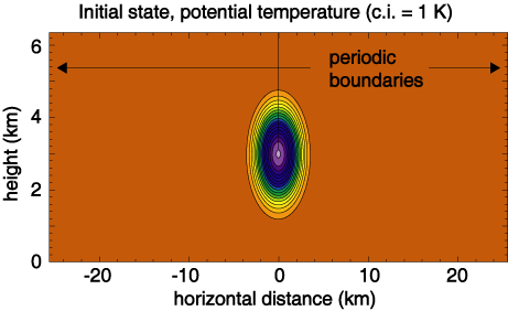
Reference (converged) solution.
____________________________________________________________________________________________
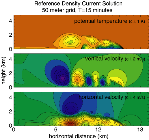
Results using 5th order upwind advection.
The additional filtering in the scheme becomes noticable as the grid
spacing is increased.
____________________________________________________________________________________________
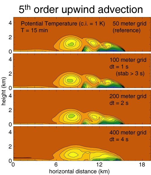
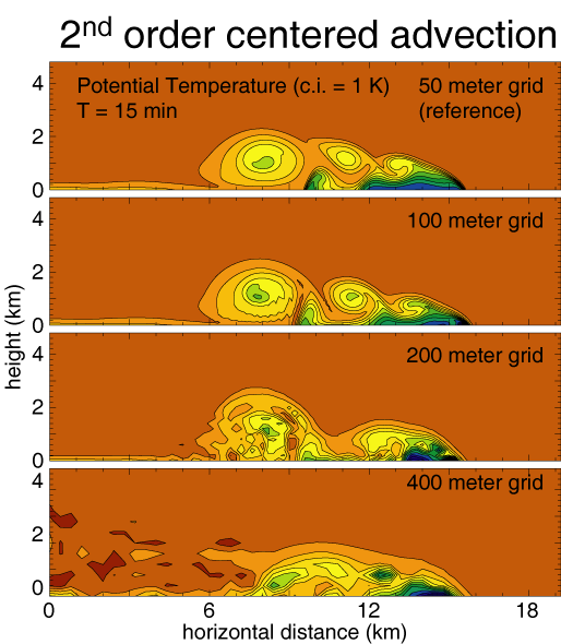
Results using 2nd order centered advection.
The lack of filtering
in the scheme becomes noticable with increased grid, and solution
errors are noticable even use dx=100 m.
____________________________________________________________________________________________
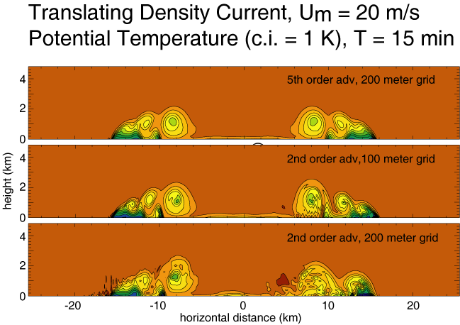
Phase errors as revealed by translation
using a mean wind U_m in a periodic channel. The solutions should
remain symmetric about the center of the channel.
____________________________________________________________________________________________
Further Discussion
There are a number of integration scheme
characteristics that these tests illuminate. One interesting
aspect of the schemes is that the front position at the end time is
well predicted even for solutions in which the gravity current is very
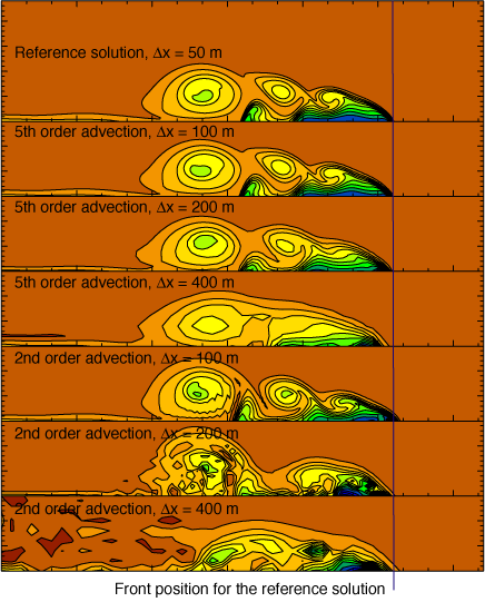
poorly resolved. As can be seen in the figure below, the front
positions (and by implcation the gravity current propagation
speed) are essentially identical for the dx-50, 100 and 200 m RK3 5th
order advection solutions. The other solutions show small errors
in position that result form the large errors apparent in the gravity
current structure.
What is also noticable is how the model using 2nd order advection
produces a very poor solution at 200 m while the 5th order scheme still
produces a reasonable facsimile of the reference (although it does wash
out the leading eddy). The second-order solutions need more
computational dissipation at grid-spacings of 100 m or more, but we
have not been able to formulate any dissipation for use with the
2nd-order scheme that produces results comparable to the 5th order
scheme. This suggests that the higher order numerics are
producing better solutions for this test.
____________________________
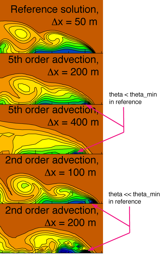
Lower order advection schemes produce noticably
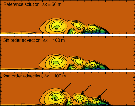
poorer solutions in the WRF-ARW model solutions. Depicted below
are the reference and 100 m solutions using5th and 2nd order advection
schemes. The 100 m solution is almost indistinguishable from teh
reference solutions when computed using the 5th order advection
scheme. Using the 2nd order scheme, the 100 m solution possesses
significant differences in eddy structure compared with the reference
solution. In particular, the eddies are too cold (see arrows
below) and the eddies shapes are different (see the first and second
eddies rearward of the leading edge). Truncation errors at
the leading edge of the gust front produce anomolously cold air which
is ingested into the eddies in the 2nd-order 100 m simulation.
The solutions suggests that the solver would benefit from more
numerical dissipation, but experiments show that problems still remain.
____________________________
The WRF-ARW advection is not monotonic. The
advection schemes produce undershoots in the potential temperature at
the leading edge of the gravity current as illustrated below. The
Lack of numerical damping is particularily pronounced for the 2nd order
advection scheme at low resolution.
|


